

Figure 2. Visible light spectrum
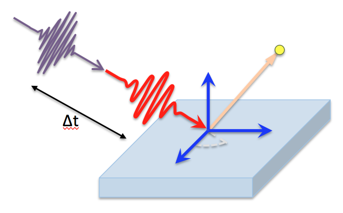
The idea is to generate these function jumps or to generate signal conversions to be able to easily quantify with an electronic device and tell us if a sample is infected by SARS-CoV-2. Below is a simulation of how the data acquisition of our system would ideally be, as well as the output in an electrical signal that we can quantify.
ESTIMATED TEST VALUES
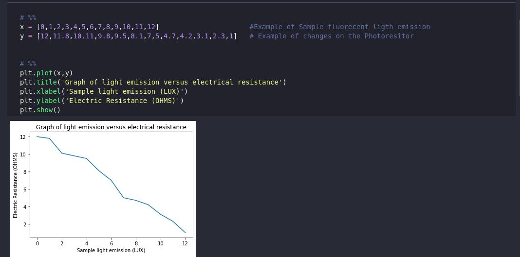
Figure 3. Graph of fluorescent emission versus electrical resistance of photoresistor
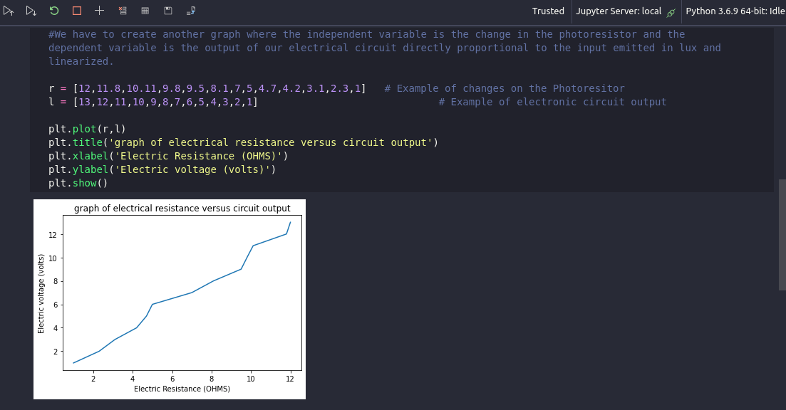
Figure 4. Graph of the electrical resistance of the photoresist against the voltage at the output of the circuit
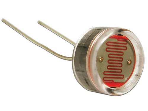
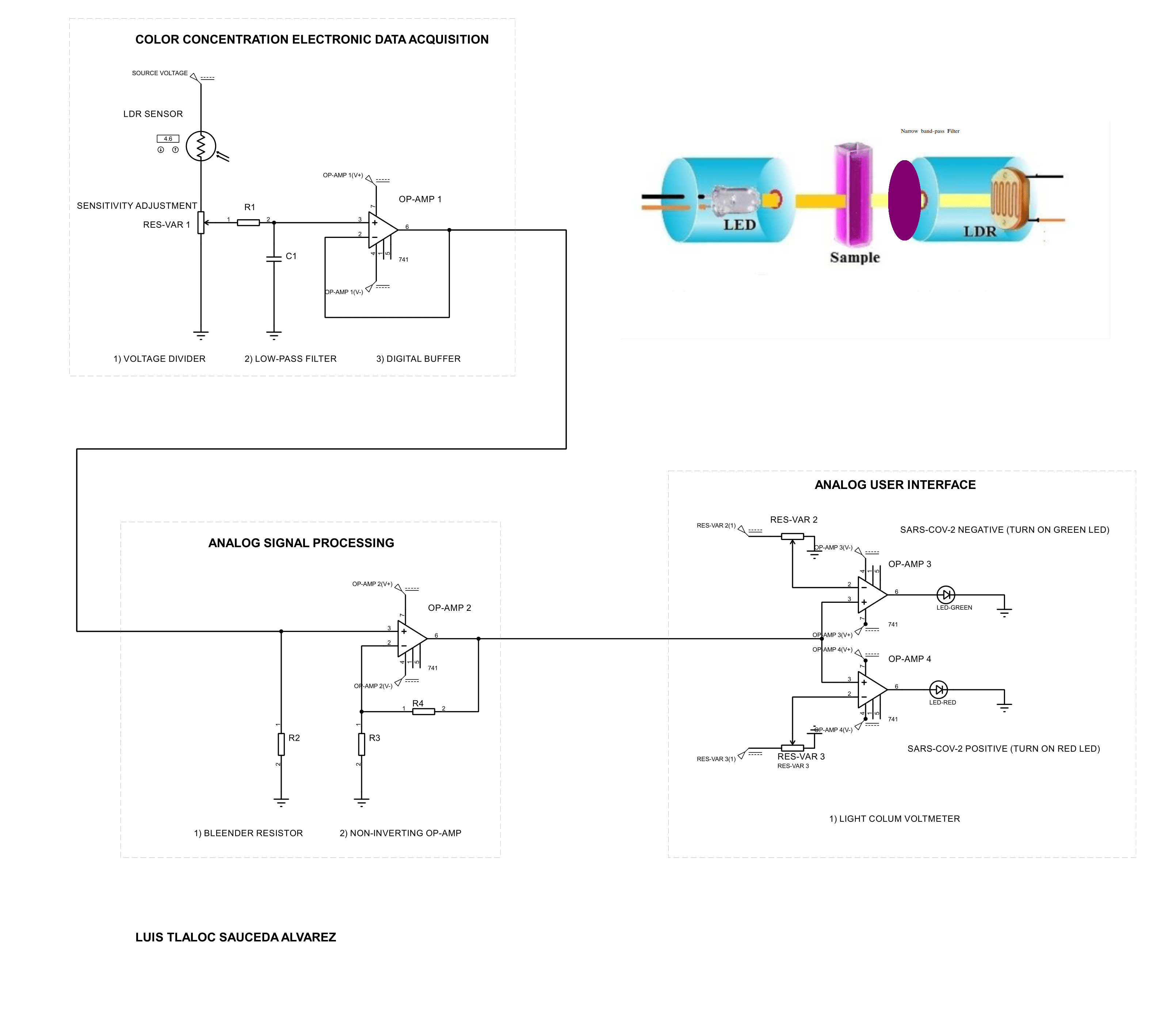
Electronic data acquisition
Below is a possible circuit to process the fluorescent light emission signal and determine whether a test is positive or negative. This system lights a green LED if the test does not have sufficient presence of the SARS-CoV-2 virus, while it lights a red LED if the detected sample is outside the established limits.
References
[1] N. Nise, Control systems engineering, 6th ed. Norman Nise, 2006.
[2] Linear ICs and Operational Amplifiers Robert F. Coughlin and Frederick F. Driscoll Prentice Hall Fifth Edition 1998